Chauffage solaire version ardoise/en
Tuto — Difficulté : Moyen — Durée : 3 day(s) — Coût : 400 EUR — Mise à jour : 21 août 2026 — 98 révision(s) — Licence : Attribution-ShareAlike (CC BY-SA)
Aires : Habitat Energie — Contributeurs : FuzzyBot, GoldofBengal, Pierreb
Fiche reformulée à partir du wiki Low-tech Lab : voir la fiche originale ↗
Versions de cette fiche : EN FR IT
Introduction
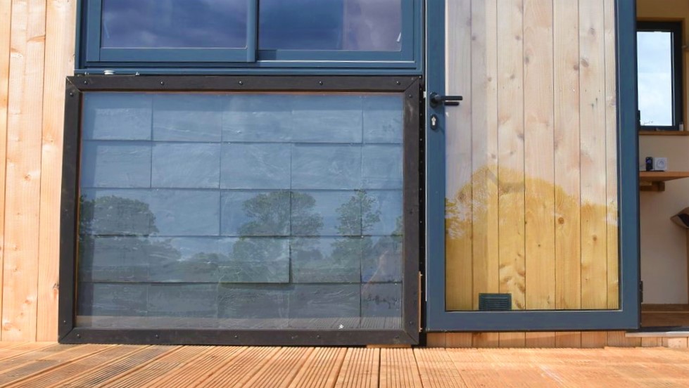
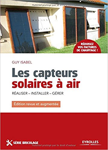
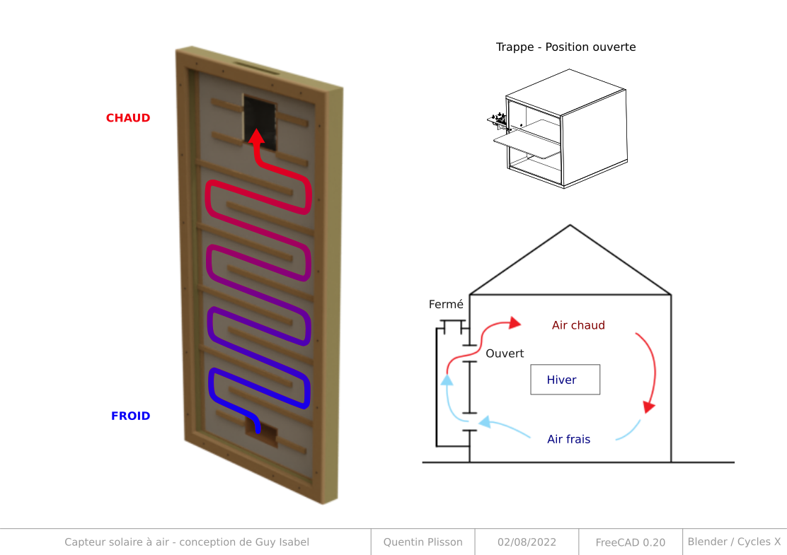
The design of this solar heating was strongly inspired by Guy Isabel, on the plans he describes in his book Les capteurs solaires à air, Eyrolles edition. The sun transmits energy to the earth by radiation. At the equator, the radiation reaches the power of 1000 W / m², it is by comparison, the power of a small electric heater. Solar energy is a free and intermittent energy, which is relatively simple to transform efficiently as heat, (yield easily above 60%). This website allows to know according to the season and the geographical position, many parameters such as the maximum power per m², the angle of the sun compared to the place. This other website makes it possible to calculate these values almost everywhere on earth by taking into account the horizon line, the orientation of the panels and other parameters. The values displayed by default correspond to the photovoltaic energy generated, but it is possible to display the radiation in kwh/m². Solar air heater Concretely, it is a question of transforming the solar radiation into heat thanks to what is called a black body (for example the very hot tar in the summer or the dashboard of a car parked in full sun). For housing, the most common systems on this principle are solar water heaters, often installed on the slopes of roofs to make domestic hot water supplements of conventional systems. Less known, the air sensor allows to heat the air of a room. This tutorial presents the manufacture of an air sensor of 2 m² designed for the heating of the air of a room of 10 to 15 m² of 5 to 7 ° C winter on average, for France. It is a complement to the conventional heating system, which allows appreciable financial and ecological savings. At a cost of around € 200, it is quickly amortized. Principle In winter, the sensor sucks in the air from below, heats it thanks to the shaving sun, then restores it to the habitat through the high outlet, at a temperature of up to 70 ° C locally instantly diluted in the ambient atmosphere. In summer, an external hatch allows to reject the hot air of the sensor outside while aspiring at the same time the air of the habitat, thus creating a natural ventilation. A valve connected to a thermostatic jack, allows to manage automatically and without electricity, the opening of the air circulation, only when it has reached more than 25 ° C in the sensor. Retrouvez dans ce rapport une analyse à l'usage de ce chauffage solaire, ainsi que des 11 autres low-techs expérimentées lors du projet En Quête d'un Habitat Durable.
Description
Solar air heater, for any type of house, by Guy Isabel.
Vidéos
Download CAO plans
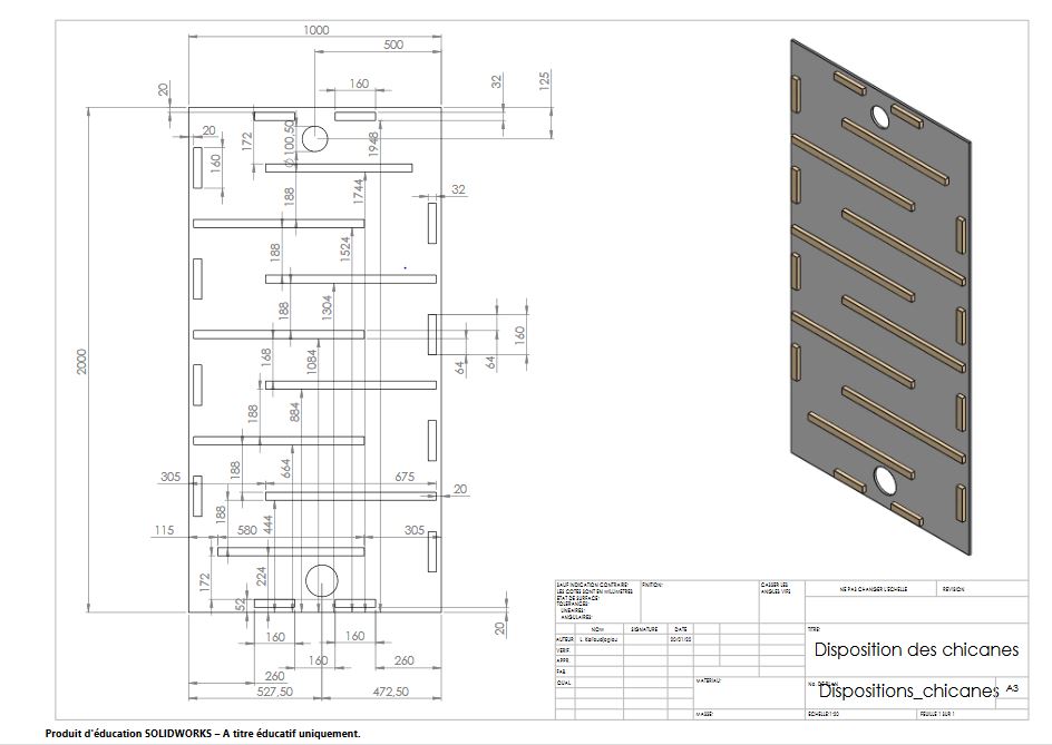
Detailed plans and CAO have been realised by Enerlog. They are available in open-source here : https://cloud.ecutsa.fr/index.php/s/apRoi395xdQb52T#pdfviewer Those plans have been used for the first version built during a workshop. They are shared here in order to respond to one of the objective of Enerlog: to support the reappropriation of the knowledge by the citizens by sharing knowledge and promote its transmission.
Modèle 3D à télécharger
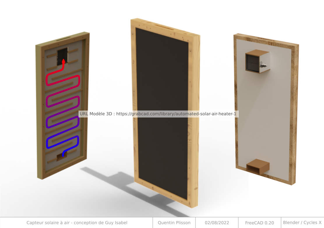
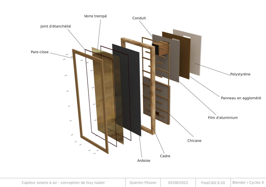
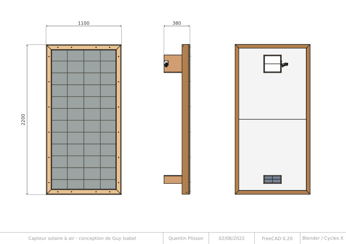
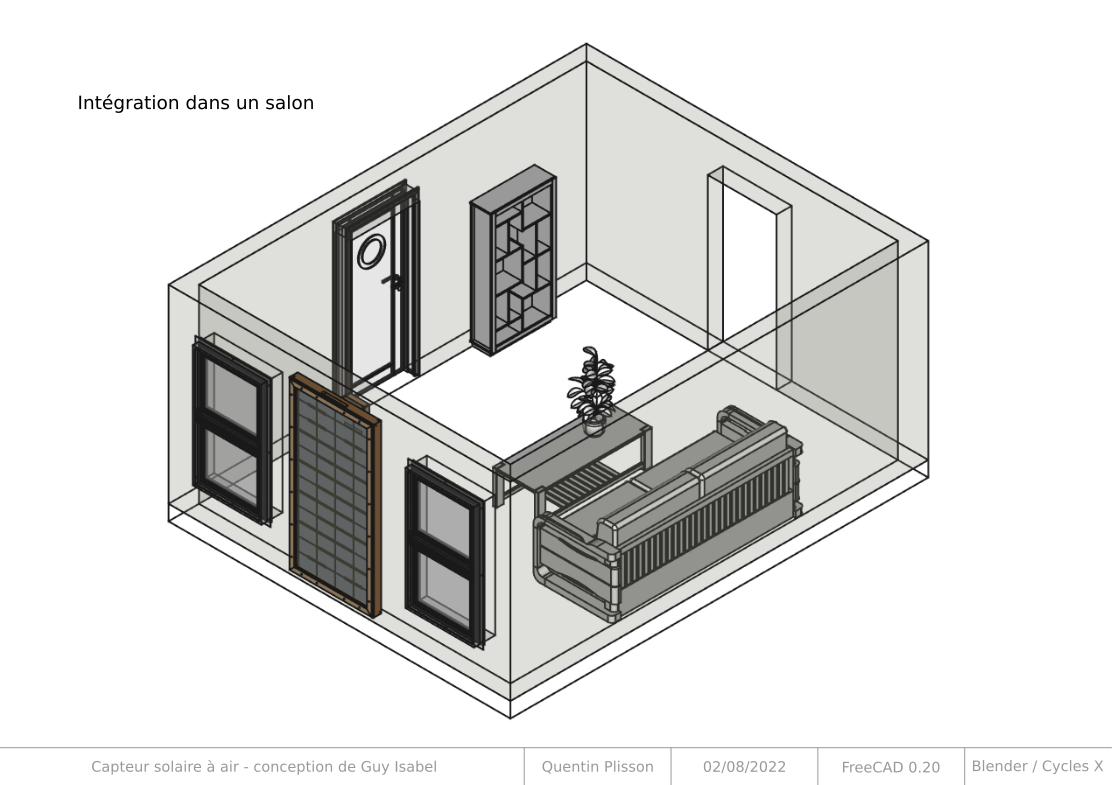
Vous pouvez télécharger un modèle 3D du chauffage solaire, au format STEP, avec des infographies expliquant le fonctionnement. Il s'agit d'une reproduction du capteur solaire à air décrit dans l'ouvrage de Guy Isabel, avec une modification seulement au niveau de la trappe. Ces plans ont été réalisés par Quentin Plisson.
Frame
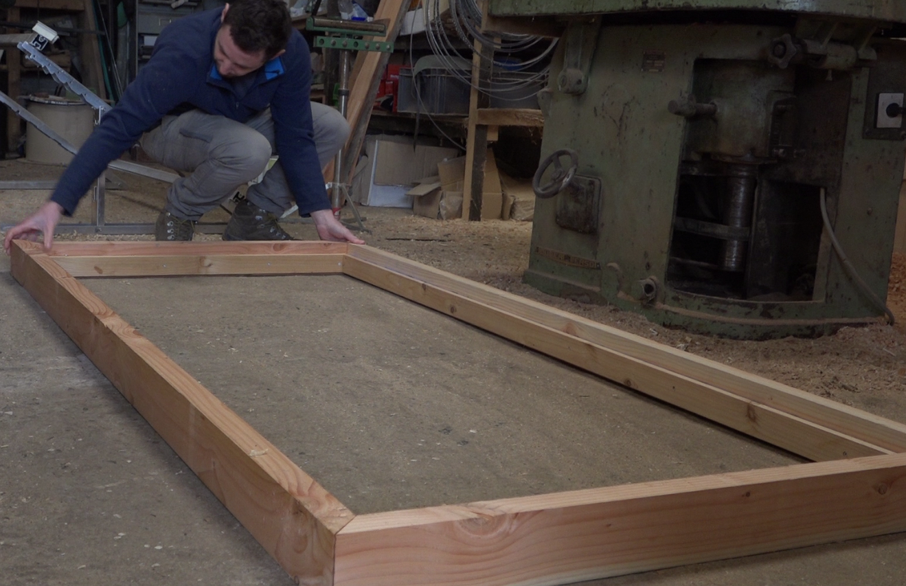
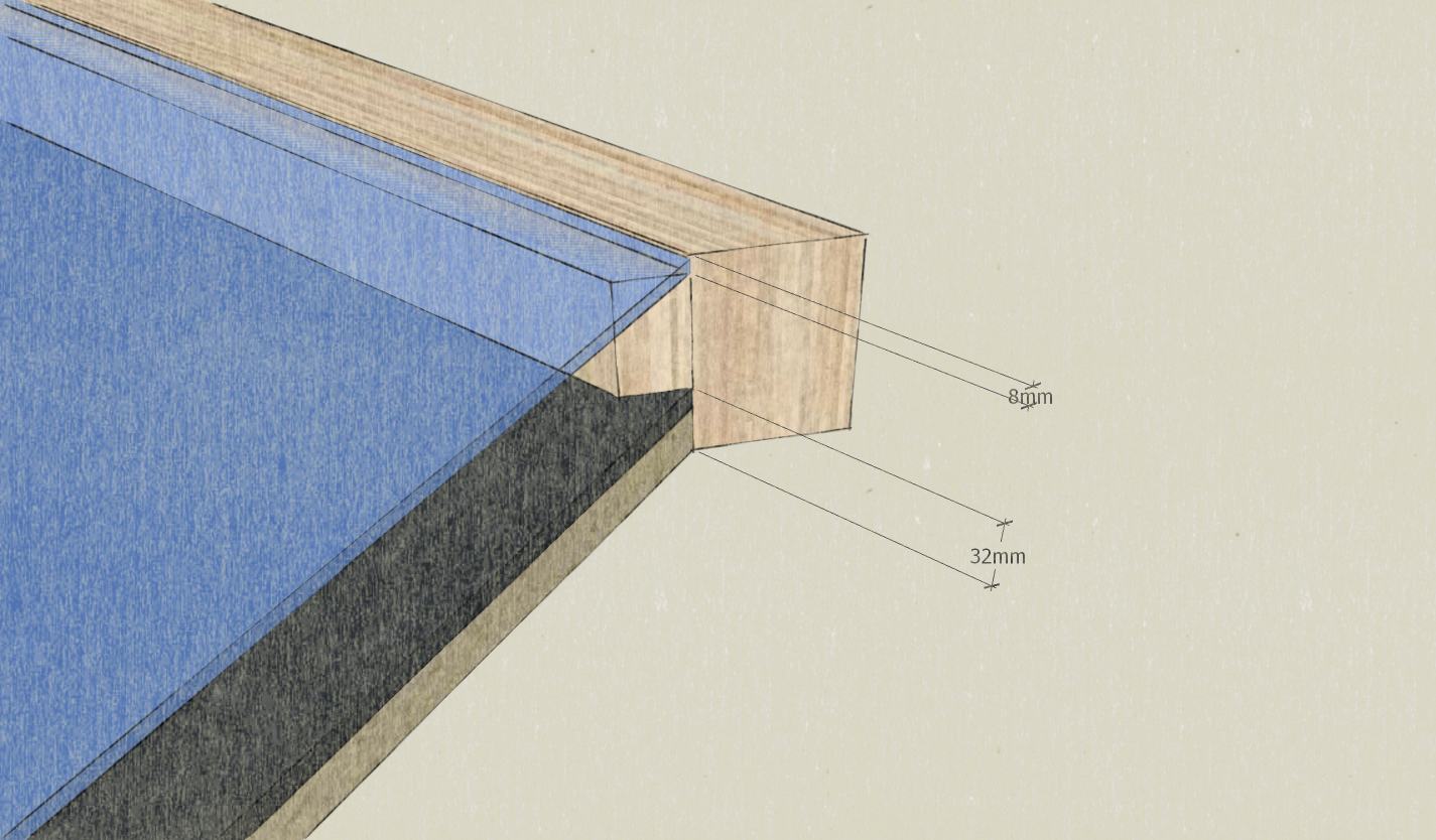
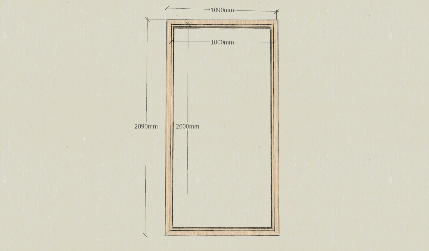
Note: Here, the frame is sized to accommodate a glass 1m x 2m by 6mm thick, a 10mm film plywood bottom and a 22mm insulating layer in STEICO. The dimensions will therefore be adapted according to the availability of each. * Prepare 2 rafters of section 93mm x 45mm and 209 cm in length. * Prepare 2 rafters of section 93mm x 45mm and 109 cm in length. * Prepare 2 battens of section 20mm x 53mm and 209 cm long. * Prepare 2 battens of section 20mm x 53mm and 109 cm long. * Glue PU glue and screw the battens on the rafters associated a face of 93mm thick, 32mm from one of the edges. Note: These 32mm correspond to the insulating thickness + filmed plywood. There is 8mm remaining on the other edge to accommodate the thickness of the glass and a seal comribande. * Cut the corners of each wood profile thus obtained at 45 °, paying careful attention to the direction of the cut. The cut is made on the length of 93mm. Note: This cut allows to find the dimension 1m x 2m of the window inside the frame. * Assemble the frame using PU glue and long wood screws in each of the 4 corners.
Background and insulation of the frame
* Prepare an area of 1m x 2m for the chosen background (here a 10mm thick film plywood). * Prepare a surface of 1m x 2m for the chosen insulation (here STEICO plates of 22mm thickness). * Pull a wood glue seal on the frame battens, 32mm thick side. * Deposit 'the bottom first' then ensure the plating with regular studding. * Draw sika cords on the bottom then lay the insulation. This is the outermost layer of the frame.
Opening the sensor input and output
Note: Here, the chosen ventilation flap is 100mm in diameter, so it is at this diameter that the inlet and the outlet will be made. * On the central axis of the sensor, trace and cut the air inlet hole, 30mm from the batten, at the bottom of the frame. * On the central axis of the sensor, trace and cut the air outlet hole, 30mm from the batten, at the top of the frame.
Optional: Rain protection
Note: Depending on the chosen insulation, the installation of a rain screen at the back is not necessarily necessary if it is well waterproof. * Remove the rain cover on the insulation layer leaving a 2cm overhang on the Douglas frame. * Staple the rain cover. * Open the rain shield at the inlet and outlet. * Glue a waterproof adhesive between the frame and the rain screen.
Summer hatch
* On the upper part of the frame, open a hatch of 300mm long by 30mm wide. It is at the bottom of the water. * Fix inside the anti-rodant grill * Using double-sided tape, center and glue a rectangle of parquet insulation on the underside of the dripstone, which serves as a cover. * Position 4 screws around the hatch taking care to check that the parquet insulation can be placed in the rectangle formed by the screw legs. * Drill the drip so that it can fit on the screw legs. * Put it aside, it will be added at the end of editing.
Reflective surface
Note: In order to reduce the energy loss in the sensor, the film plywood bottom is covered with an aluminum layer to reflect the infrared radiation in the sensor. * Line the bottom of the aluminum adhesive sensor.
Glass weatherstrip
* Place an adhesive joint on the battens of the frame 1mm from the edge, all along the frame. It will serve to welcome the glass.
Baffle circuit
* Screw the 30mm x 16mm battens to the reflective part in a baffle pattern. * The baffles, by 675mm, cover 3/4 of the width of the panel. Note: Here, the gap including 2 cleats is 220mm, this is the width of the slates used later. This spacing will allow a slight recovery of each slate. 'Note' : Here, the gap including 2 cleats is 220 mm, this is the width of the slates used later. This spacing will allow a slight recovery of each slate.
Slate laying
* Position the first slate rack on the lowest level of baffle. * Mark 2 holes and drill with a 4mm drill. It is possible to slightly mill the holes with a wider drill so that the screw head is integrated in the thickness of the slate. * If necessary, cut the slates with the diamond disc grinder, a hacksaw can possibly do the trick. * Complete the slate frame, taking care to raise the slates on the baffles closest to the exit (see photo). Note: The row of slate is raised near the exit so that the air in front of and behind the slates can be evacuated, both in winter and in summer by the "summer hatch".
Oiling and varnishing
* Oil the frame with linseed oil. * Let dry and then varnish.
Installing the glass
Note: Here, a tempered glass 6mm thick is used. It is also possible to use polycarbonate. * Clean the glass. * Prepare the beading in the rest of battens of 53mm x 20mm. A chamfer is made for a good water evacuation and a 45 ° cut as for the frame. Oil and varnish the screens. 'Note:' The baffles are used to hold the glass in its housing by compressing the compression joint. They must both cover the edge of the glass and rest on the frame. * Pull a silicone gasket between the compression seal and the frame. * Position the glass. * Pull a silicone seal again on the edge of the glass as well as on the frame. * Position and screw the baffles. * Pull a silicone bead on the glass edge / beading .
Valve system, fixed part
Note: The thermostatic cylinder works without electricity. It contains a calibrated material that expands from 25 ° C and retracts below. * Limer the internal pointing of 12mm and 14mm copper sleeves * Split the length of the 14mm sleeve. * Insert the cylinder into the 12 mm sleeve and all into the 14 mm sleeve. * Insert this assembly into the brass nipple 15/21. * Close the bottom side of the cylinder by aiming a blind nut on the nipple. * Screw the open nut onto the other side of the nipple.
Valve system, moving part
* Cut 100mm of brass tube diameter 4mm. * Insert a screw and a washer at one end. * Drill a 15/21 brass nut in the center with a 4mm drill bit. * Insert the spring and the drilled nut on the tube. * Remove the plastic part of a domino diameter 4mm and screw it on the free end of the brass tube. * Prepare a small fork in thick copper wire and place it on the domino. * A brass threaded tube 15/21 is used to hold the moving part thus created. Cut this tube so that once screwed into the fixed part, the spring is slightly compressed when the cylinder is retracted (cold). * Assemble everything without forgetting to pass 2 nuts around the threaded tube. * Glue the fixed part of the ball catch onto the flat of the 2 nuts of the threaded tube.
Valve system, Assembly
* Prepare a stainless steel tube of the width of the wall where the sensor will be installed. (here, a 100mm diameter tube is used) * Position the valve at one end of the tube, the opening to the outside * Mark the positioning of the cylinder assembly, hot and completely out , so that the copper fork pushes the fins in maximum opening. * Rivet the ball portion of the latch to this position. * Place the tube in the wall, at the air outlet of the sensor, the flap towards the habitat.
Installation
* Glue a compound seal around the entrance and exit holes on the habitat. * Position the sensor support brackets on the wall, at the bottom and at the top, then screw the sensor tightly to the wall so that the compression joints are stressed.
use
Winter : * Leave the hatch closed. * The grazing winter sun shines on the slates that will heat the sensor enclosure. * By "thermosyphon" effect, the warm air will naturally rise, creating a draw sucking the air of the habitat from the bottom of the sensor. * Circulation will only be allowed by the valve when the temperature in the sensor will exceed 25 ° C. Summer: * Open the summer hatch * The sun shines on the slates that will heat the system. * The air will naturally go up and escape out through the summer hatch. * A suction through the bottom hole of the sensor will allow to evacuate the air of the habitat thus creating a natural summer ventilation.
Contenu pédagogique à télécharger
Vous pouvez télécharger une fiche pédagogique créée par le Low-tech Lab à l'occasion de l'exposition "En Quête d'un Habitat Durable" dans la partie "Fichiers" du tutoriel (onglet au niveau de la section "Outils-Matériaux")
Accompagnement & Formation
Enerlog souhaite accompagner les transitions vers des modes de vie plus soutenables en développant l’autonomie et la résilience énergétique. Pour cela, la SCIC met à disposition ses compétences dans le domaine de la thermique, du numérique et de l’énergie pour faire émerger des solutions low-tech adaptées à différentes problématiques. La structure propose des formations, des solutions clé en main, et diffuse en accès libre de la documentation sur ses travaux de R&D

← Retour au répertoire — Fiche originale sur wiki.lowtechlab.org ↗